Measuring an electrical installation: voltage, continuity, polarity, and why you measure before you touch
What a multimeter reading means on L, N and PE, why a switched-off breaker is not proof that a circuit is dead, what continuity and insulation tests check, and why reversed polarity leaves appliances live when they are off.
Also in: Polski · Português (Brasil) · Deutsch
Electricians have a saying: a circuit is live until you have proved it dead. Not until the breaker is off, not until the label says so. Proved, with an instrument. This article explains what the usual measurements on an installation show, and why each one exists. It is not a how-to for working on your own wiring: that takes training, the right instruments, and in most countries a qualification.
Why "the breaker is off" is not enough
Switching off the breaker marked "kitchen" leaves a circuit live more often than you would think:
- the board's labels are wrong, or the circuit was extended from another one;
- a borrowed or shared neutral carries current from a circuit that is still on, so the "dead" neutral is not dead;
- the switch or breaker is in the neutral instead of the line, so the circuit is off but still live;
- there is a second supply: a generator, a solar inverter, or a feed from another board.
That is why the rules for safe work (EN 50110-1 in Europe, NR-10 in Brazil) all include the same core steps: disconnect, secure against reconnection (lock it off), verify that there is no voltage, and only then work. In Germany these are taught as the fünf Sicherheitsregeln, the five safety rules.
The right instrument for proving dead
Trained electricians prove a circuit dead with a two-pole voltage tester (to EN 61243-3) or a multimeter rated for installation work (CAT III or CAT IV for the voltage involved), with fused leads and shrouded probes. The UK's GS38 guidance describes such leads in detail.
Two habits matter more than the brand:
- Prove the tester on a known live source before and after the test. A tester that shows 0 V may be broken.
- Test every combination: L–N, L–PE, and N–PE. A single L–N reading misses a line that is live with respect to earth.
A non-contact "voltage pen" is useful for a first look, but it is not proof that something is dead.
Reading voltages on L, N, and PE
On a healthy single-phase circuit on a 230 V supply, the three readings look like this:
| Between | Healthy reading | What a different reading suggests |
|---|---|---|
| L and N | about 230 V | 0 V: no supply reaches this point, or the neutral is open |
| L and PE | about 230 V | 0 V or far less: the protective conductor is missing or open |
| N and PE | near 0 V, a few volts under load | Tens of volts or more: a lost neutral, a broken PEN, or a serious fault |
On a three-phase supply, phase to phase reads about 400 V. In Brazil the numbers depend on the region: 127 V or 220 V from phase to neutral.
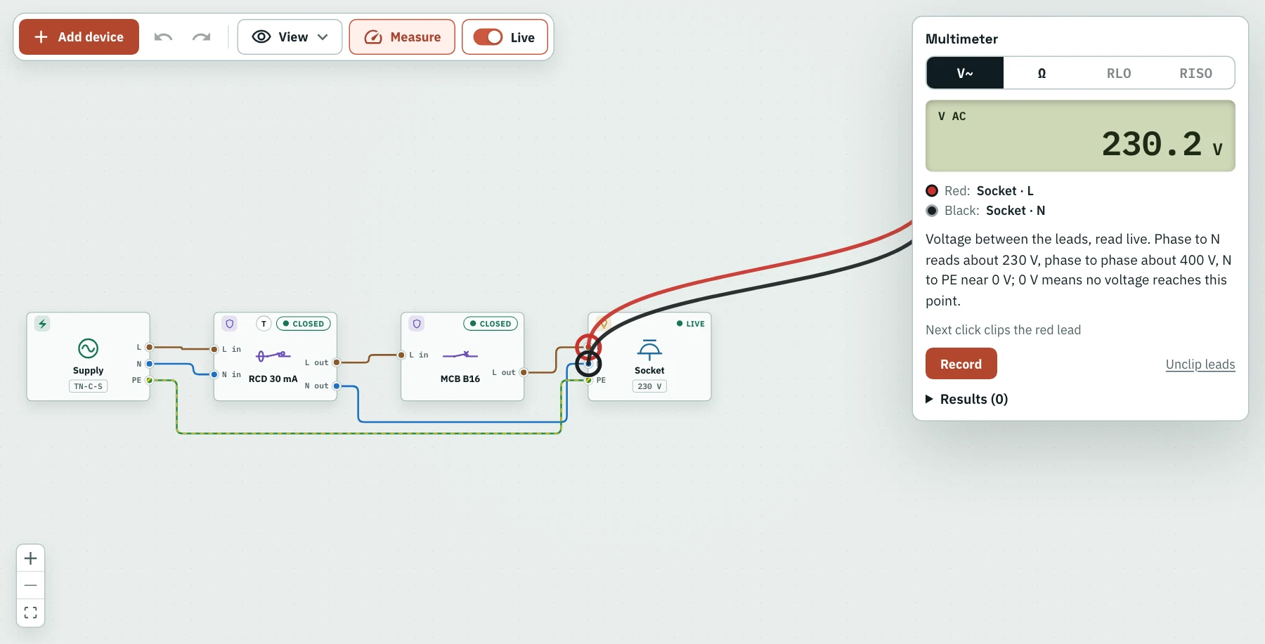
Measure mode: the multimeter's leads on a socket's L and N read about 230 V. Move the black lead to PE and it should read about the same; N to PE reads close to 0 V.
Resistance and continuity: only on dead circuits
A multimeter's Ω range sends a small current of its own and measures the result. That only means something on a circuit with no voltage on it. With voltage across the leads, the reading is meaningless, and a cheap meter can be damaged. A good meter warns you.
On a dead circuit:
- a continuous conductor reads a fraction of an ohm;
- a load, such as a heater element, reads its own resistance;
- OL (over limit) means nothing connects the two points: the circuit is open.
For proper installation testing, a multimeter is not enough. Protective conductor continuity is measured with a test current of at least 200 mA (IEC 61557-4), because a strand-thin connection can still pass a multimeter's tiny current. Insulation resistance needs a DC test voltage, usually 500 V for 230/400 V circuits. Both are done with an installation tester.
The tests an installation gets
IEC 60364-6 lists the verification of a new installation in an order that goes from dead tests to live ones:
| Test | Supply | What it proves |
|---|---|---|
| Continuity of protective conductors | Off | Every PE terminal really connects to the main earth, with low resistance |
| Insulation resistance | Off | No path between conductors, or to earth; at least 1 MΩ at 500 V DC for 230/400 V circuits |
| Polarity | Off or on | Switches and single-pole devices are in the line, not the neutral |
| Earth fault loop impedance | On | A fault current is large enough for the device to disconnect in time |
| RCD operation | On | Each RCD trips within its time at its rated residual current |
| Functional tests | On | Switches, RCD test buttons, and controls work as intended |
National versions follow the same pattern: PN-HD 60364-6 in Poland (with periodic inspection at least every five years under the building law), DIN VDE 0100-600 in Germany, BS 7671 Part 6 in the UK, and section 7 of NBR 5410 in Brazil.
Polarity: why a swapped L and N is dangerous
Swap line and neutral at a socket or a light, and in most cases everything still works. The lamp lights; the kettle boils. That is exactly the problem:
- Single-pole switches in appliances and light fittings now interrupt the neutral. The appliance is off, but its insides are still at line voltage.
- In an Edison-screw lamp holder, the outer thread that you can touch while changing a bulb becomes live instead of the centre contact.
- A fuse or single-pole breaker in the neutral would open the circuit on a fault and leave it live.
Schuko (type F) plugs can be inserted either way round, so appliances for those countries are designed to be safe with either polarity. Fixed wiring is different: switches and protective devices must always be in the line. That is what the polarity test checks.
Practise the measurements without the risk
WireWhy has a Measure mode with the instruments an electrician uses. Clip the multimeter's red and black leads onto any two terminals to read AC voltage or resistance; switch off the part you are measuring and see the reading change; leave it live on the Ω range and the meter warns you, as a real one would. The installation tester measures protective conductor continuity at 200 mA and insulation resistance at 500 V DC, and refuses to test when it finds voltage. Every reading can be recorded in a results table in IEC 60364-6 order, with its limit and a pass or fail.
Open the canvas at wirewhy.com/app, build a small board, and measure it. To understand what the readings tell you, see also TN-C-S, TN-S and TT earthing systems explained simply and Why does my RCD trip?
Your turn
Build this circuit in the simulator
Free, no account needed. It opens in the simulator.
Open the simulator →