One RCD or two? How to split a flat's consumer unit so one fault doesn't switch everything off
A single 30 mA RCD for a whole flat protects people, but any leak anywhere puts every light out. How to split a consumer unit across two RCDs or RCBOs, how to group the circuits, the neutral mistake that trips them as soon as a load comes on, and the right order of devices in the board.
Also in: Polski · Português (Brasil) · Deutsch
A reader sent us a photo of the consumer unit in their flat: a 2-pole 40 A main isolator, a surge protection device, one 30 mA type A RCD, and three MCBs behind it, C16 for the air conditioner, B16 for the sockets and B10 for the lighting. Nothing is wrong with it. Every circuit has 30 mA protection and a breaker sized for its cable.
The problem is what happens when something leaks. A damp balcony socket, a tired washing machine heater, a kettle with a cracked element: the one RCD trips and the whole flat goes dark, lights included. Usually at night, and you find the board by the light of your phone.
The fix is not a less sensitive RCD. It is dividing the installation so that one fault takes out only part of it.
The principle: divide the installation
IEC 60364-1, the base of most countries' wiring rules, has a short clause on the division of an installation (314). It says an installation is divided into circuits as needed to avoid danger and minimise inconvenience in the event of a fault, to make inspection and maintenance safe, and to account for the hazards of a single circuit, such as lighting, failing. BS 7671 has the same text in Regulation 314.1, and adds reducing unwanted RCD tripping caused by protective conductor currents.
One RCD for everything avoids danger. It does not minimise inconvenience, and losing all the lighting at night is more than an inconvenience: people fall down stairs in the dark.
That last point is the second reason to split. Computers, chargers, LED drivers and anything with a mains filter leak a little current to earth by design, and on one RCD it all adds up. As we explained in why an RCD trips, a rule of thumb is to keep standing leakage below about 30 % of IΔn, under 9 mA on a 30 mA device. Two RCDs each carry roughly half the background leakage, which leaves more margin before a small real fault tips one over.
Three ways to split
| Option | On a fault | Cost and space |
|---|---|---|
| Two (or more) RCDs, each feeding a group of MCBs | Only that RCD's group goes off | Moderate: one extra 2-module device per group |
| An RCBO for every circuit | Only the faulty circuit goes off | Highest, though slim 1-module RCBOs keep the board small |
| Mixed: RCDs for groups, RCBOs for a few circuits | Depends on the circuit | In between |
RCBOs give the best availability: a leak in the washing machine switches off the washing machine and nothing else. Two RCDs are the usual compromise in a flat, and a big step up from one.
How to group the circuits
The aim: whichever RCD trips, you still have light and the essentials keep running.
- Never put all the lighting behind one RCD. Split the lighting circuits between the RCDs, or keep lighting on one RCD and the circuits most likely to leak on the other.
- Separate the wet and heavy loads. Kitchen, bathroom and washing machine, air conditioner or heat pump: real leaks come from here, so do not stack them all on one RCD.
- Think about the fridge and freezer. Put them on the RCD least likely to trip, or on their own RCBO.
- Do not overload an RCD. Its rated current (40 A is usual in a flat) should not be lower than the fuse or breaker ahead of it.
A sample layout for a single-phase 230 V flat:
| Circuit | MCB | Cable | RCD |
|---|---|---|---|
| Lighting: living room, bedrooms | B10 | 1.5 mm² | RCD 1 |
| Sockets: living room, bedrooms | B16 | 2.5 mm² | RCD 1 |
| Bathroom and washing machine | B16 | 2.5 mm² | RCD 1 |
| Lighting: hall, kitchen, bathroom | B10 | 1.5 mm² | RCD 2 |
| Kitchen worktop sockets, fridge | B16 | 2.5 mm² | RCD 2 |
| Dishwasher | B16 | 2.5 mm² | RCD 2 |
| Air conditioner | C16 | 2.5 mm² | RCD 2, or its own RCBO |
Cable sizes depend on installation method and length, and a hob or oven gets its own circuit sized to the maker's instructions. In the UK the sockets would usually be 32 A ring finals in 2.5 mm²; the grouping logic is the same.
For the reader's three circuits, the smallest useful change is a second RCD: lighting on one, sockets on the other, and the air conditioner wherever it balances best, or on an RCBO. One caution first: in older flats the neutrals of two circuits are sometimes joined in a junction box. Splitting them across two RCDs will not work until each circuit has its own neutral all the way.
The mistake that trips the RCDs: neutrals
A board with one RCD has one neutral bar. A board with two RCDs needs two neutral bars, one per RCD, and every circuit's neutral goes back to the bar of the RCD its line comes from. Getting this wrong is the most common error when a second RCD goes in.
If a circuit takes its line from RCD 2 but its neutral lands on RCD 1's bar, the current leaves through RCD 2's ring and comes back through RCD 1's. RCD 2 sees current going out that never returns; RCD 1 sees current returning that never went out. As soon as anything on that circuit is switched on, both see the whole load current as residual current, far above 30 mA. The faster one opens first and breaks the circuit's path, so the other may stay closed; in a real board both often drop. Either way the circuit is dead, and replacing an RCD changes nothing: the fault is the neutral, not the RCD.
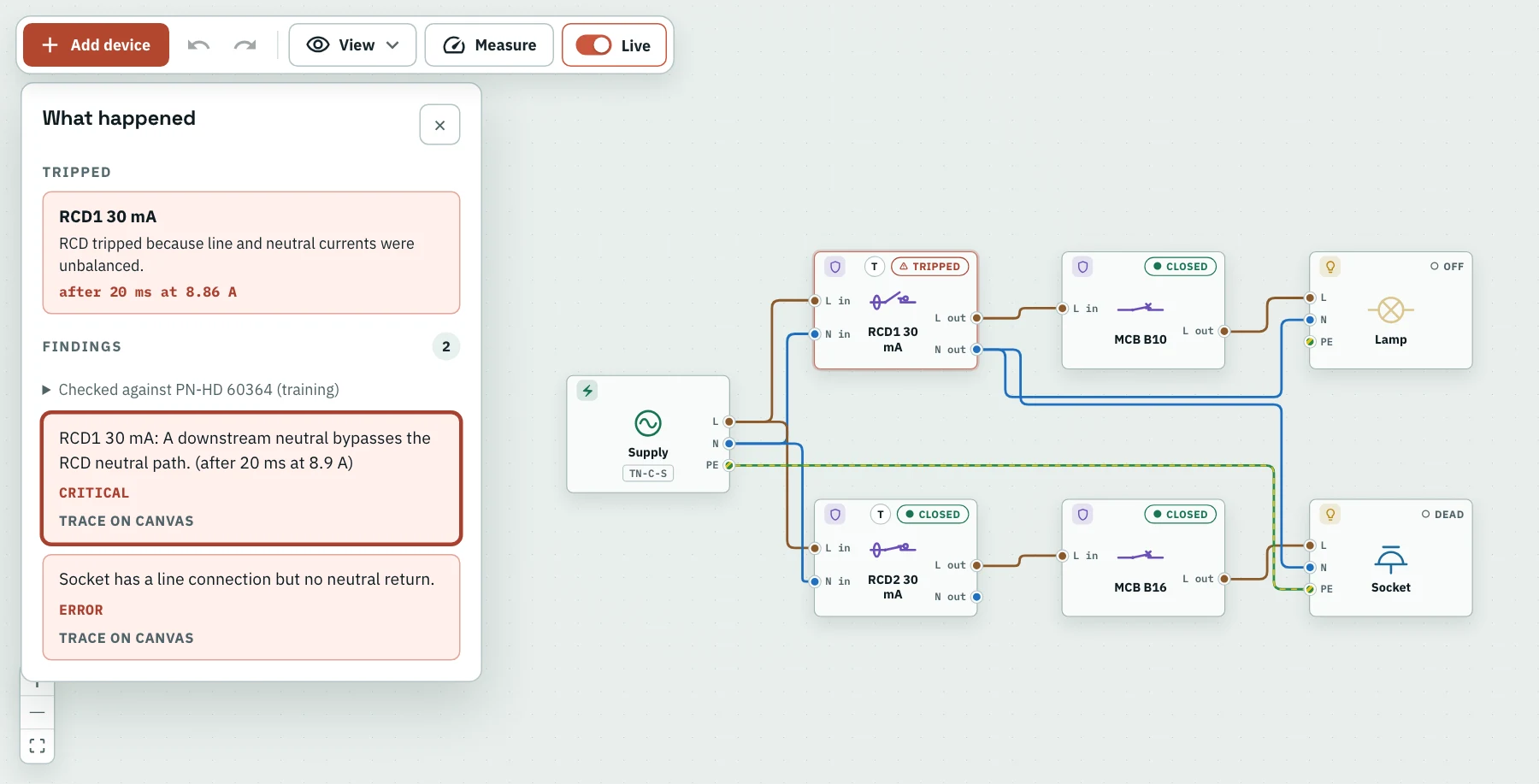
The socket circuit takes its line from RCD 2 but its neutral from RCD 1's side. With the heater on, RCD 1 opens first, in 20 ms at about 8.9 A of residual current, which cuts the socket's return path, so RCD 2 stays closed. The "What happened" panel names the tripped RCD and adds that the socket has a line but no return through the neutral; "Trace on canvas" numbers the wires of the current that crossed between the two RCDs.
The same happens with a neutral taken from before the RCDs, or with circuits from different RCDs sharing a neutral in the walls. The rule from the RCD article holds: a circuit's neutral comes from the same RCD as its line, and nowhere else.
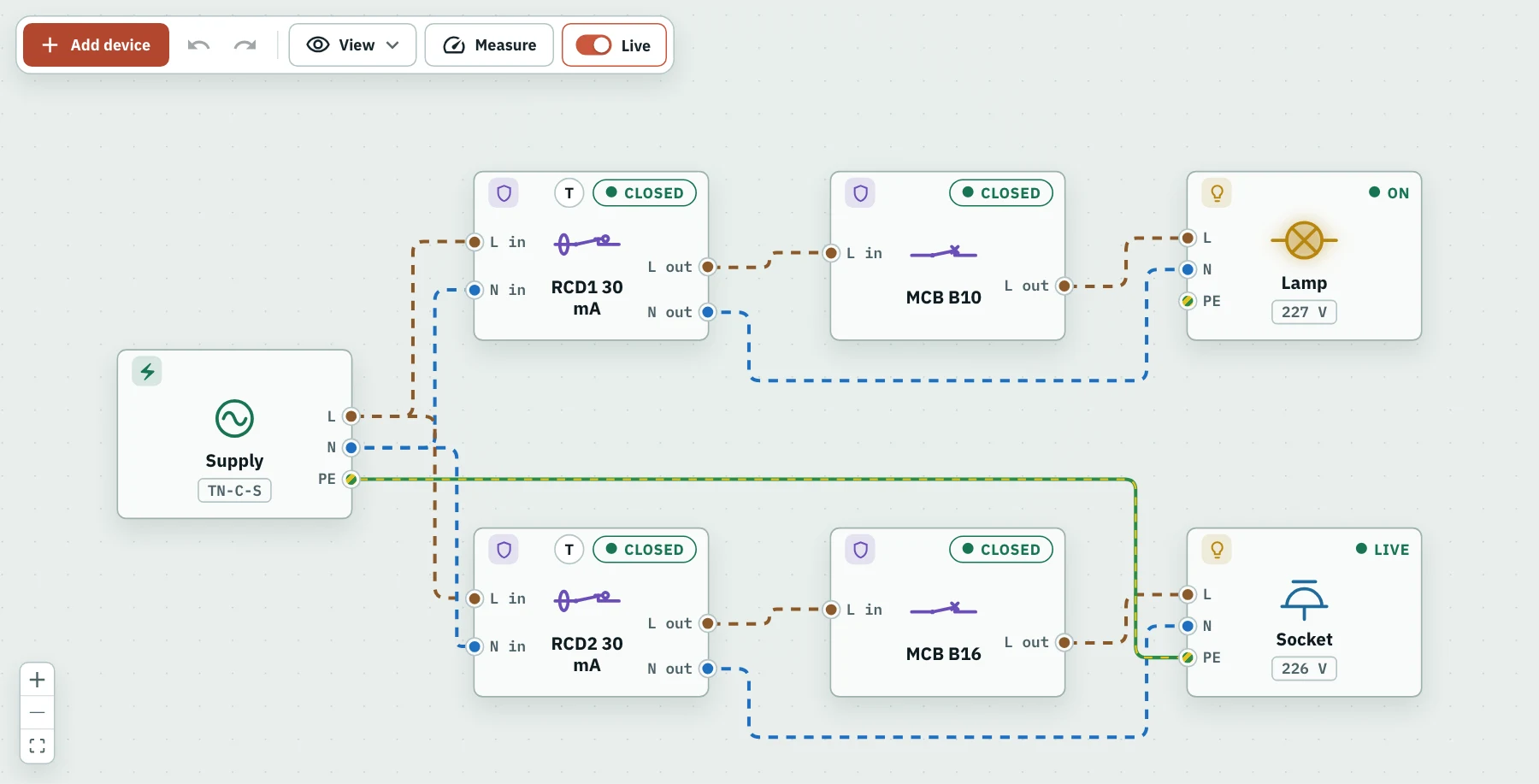
The same board wired correctly: lighting on RCD 1, a socket with a 2 kW heater on RCD 2, each neutral back to its own RCD. Everything is on and no wiring problem is found.
The order in the board
- Main isolator. It switches off the whole board, the surge protector included. With a three-core supply (line, neutral and a separate PE, so TN-S in the flat), a 2-pole isolator that also switches the neutral is fine, and better for isolation. Only a combined PEN conductor (TN-C) must never be switched; in a TT installation, switching the neutral is expected. See earthing systems.
- Surge protection device (SPD). Before the RCDs, not after. A surge diverted to earth behind an RCD is a residual current, so the RCD can trip in every thunderstorm, and the surge can damage it. Keep the SPD's leads short, about 0.5 m in total from the live conductor to the SPD and on to the earth bar, and fit the backup fuse or breaker its maker specifies. In TT, use the maker's TT connection, with a spark gap between N and PE.
- RCDs, each feeding its group.
- MCBs, one per circuit, behind their RCD. An RCBO replaces an RCD and MCB together.
A selective RCD (type S) belongs upstream only when RCDs are cascaded, for example 100 mA type S at the origin and 30 mA below. A plain 30 mA RCD ahead of other 30 mA RCDs gives no selectivity: either may trip, often both.
Which type: A, F or B
Type A, which also detects the pulsating DC leakage from electronics, is the sensible minimum; type AC is no longer accepted in some countries. Some manufacturers ask for type F for inverter-driven air conditioners, heat pumps or washing machines, and an EV charger needs type B, or type A together with the 6 mA DC detection many chargers have built in. Follow the appliance's installation instructions rather than upgrading everything: smooth DC leakage can blind a type A RCD upstream of a type B one.
In the UK
BS 7671 requires 30 mA RCD protection for socket outlets up to 32 A, for cables buried shallowly in walls, and for lighting circuits in homes, which in practice covers almost every domestic circuit. Split-load boards with two RCDs used to be the default; RCBO boards are now common, and "high integrity" boards mix both. A new domestic consumer unit must have a non-combustible enclosure.
Who does the work
Adding a second RCD means re-terminating neutrals in the board and testing every circuit afterwards, RCD trip times included. That is work for a qualified electrician, and in many countries it must be certified. What you can do is understand the plan and check that the result makes sense.
Try it in WireWhy
Build the reader's board: a supply, a 2-pole main isolator, an SPD, two 30 mA RCDs, an MCB under each, a lamp on one and a socket with a heater on the other. Switch everything on and it works. Now move the socket's neutral to the wrong RCD's side and switch the heater on: the RCDs see the whole heater current as residual current, the faster one trips, and the "What happened" panel numbers the wires the current took between them. Move it back and put an earth fault on the heater: only its RCD trips, and the light stays on.
Open the canvas at wirewhy.com/app and try it: it is free and needs no account.
Your turn
Build this circuit in the simulator
Free, no account needed. It opens in the simulator.
Open the simulator →